The Slider Buffer Installation Guide Copyright 2002 Nomad Radio
Three questions here. Do any of them sound familiar?
1) When I turn the channel selector on my Browning Mark III SSB transmitter to select my Glenn slider, the power will drop. Even when I set it to (for example) channel 20, the transmitter is stronger on CRYSTAL channel 20 than it is with the Glenn set to 27.205
2) When I switch my Siltronix 90 slider from 'CB' band to 'HF' band, the transmitter power drops WAY off.
3) This little resistor under the chassis just beneath the channel selector overheats and burns up every time I replace it.
This is a pretty simple proposition, really. All the sliders sold in the mid-to-late seventies BUT a couple were made to properly drive a solid-state radio. The two exceptions to this were 1) the PAL slider. It could be persuaded to drive a tube radio okay on its own, and had a small trimpot inside to reduce the drive, making it correct for a solid-state radio, as well. And 2) Maco made a 5 MHz slider that fed directly into one of the two oscillator tubes on the Mark III SSB. It had other annoying problems we won't cover here.
You plucked a crystal out of the radio, and wired in a cable. The slider would feed a variable frequency into that cable, taking the place of the fixed quartz crystal. A solid-state radio runs from 12 volts, more or less, and the drive level from the crystal is a couple of volts, about one-sixth or so of the power supply that runs it.
Tubes, on the other hand run from 100 to 200 volts, and the same one-sixth fraction of that is a LOT more than a couple of volts. That's all the Siltronix and Glenn sliders would deliver. This causes the transmitter to be "wimpy". It just isn't getting enough drive.
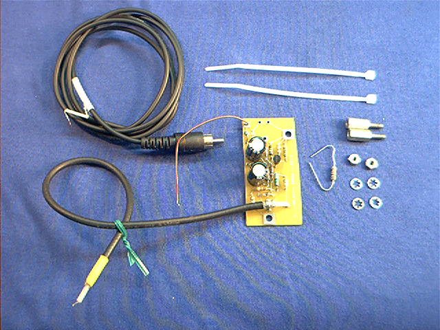
Packing list:
2) 4-40 x 1/2 in. threaded standoff
4) #4 inside tooth lockwasher
2) 4-40 hex nuts
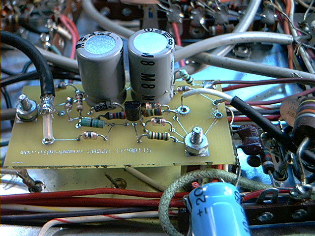
1) SB-1 Slider Buffer board w/power and output
leads
attached.
1) 4 ft. long low-capacitance (80 pf) shielded
cord wih
RCA plug on one end, stripped/tinned on the other.
1) 10K ohm 1/2-watt resistor to replace R34, if
needed.
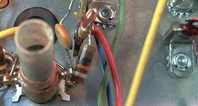
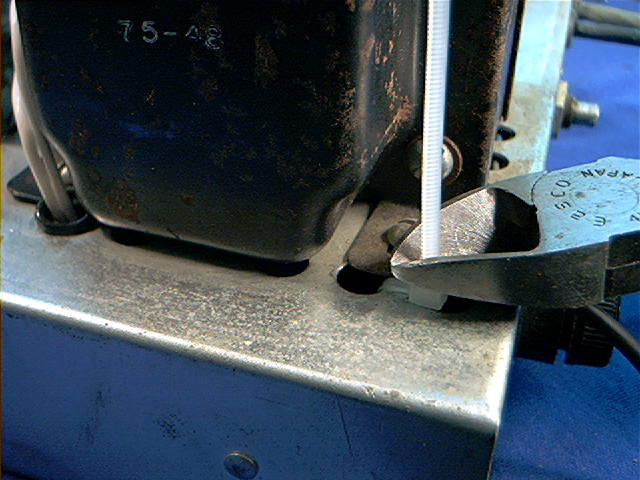
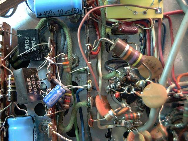
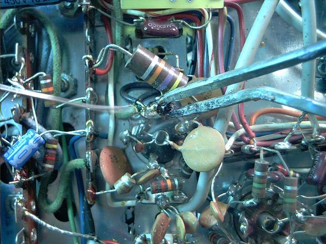
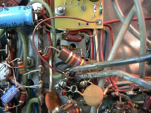
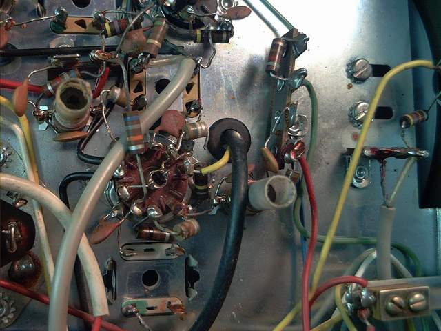
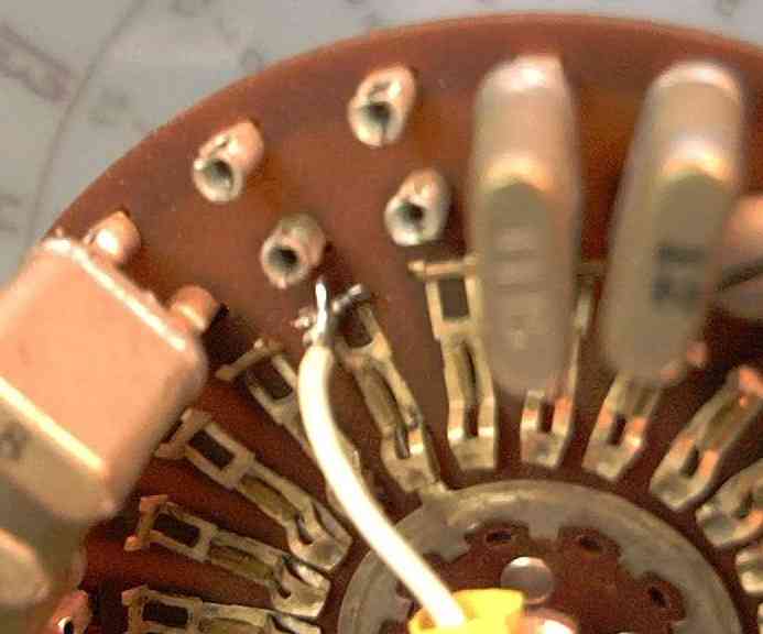
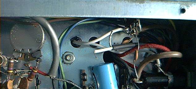
Before changing anything under the radio, it's a good idea to check for a routine weak spot. Just underneath the channel selector, under the chassis is a slug-tuned coil, L5. It has two solder lugs on it. The front-facing lug has a 1/2-watt resistor with brown-black-orange color-coding stripes. There may be a silver or gold band after the orange one. This is R34 on the schematic. The original value is 10K (10,000 ohms). If the orange band is faded or dark, this indicates stress. The part may be okay, but if it is darkened or discolored, dont' trust it. R34 routinely gets overheated when a Siltronix slider is used with a direct hookup. If it doesn't look PERFECT, replace it with the one we provided with the buffer. It's a really good idea to check V6 the 6GH8A tube. If R34 gets stressed, V6 does, too.
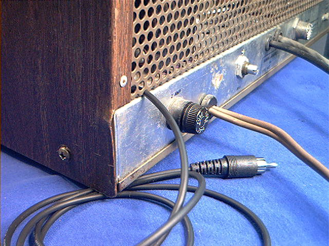
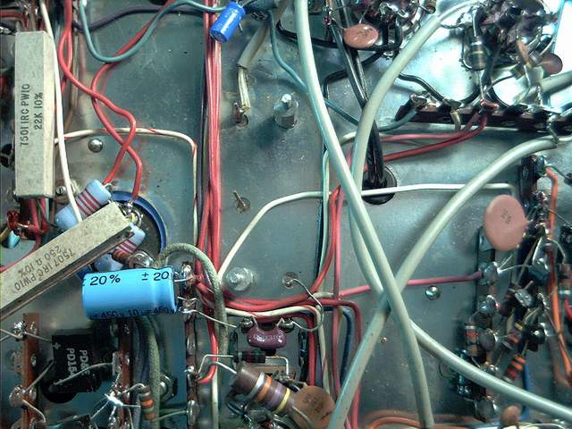
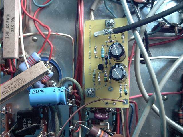
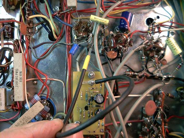
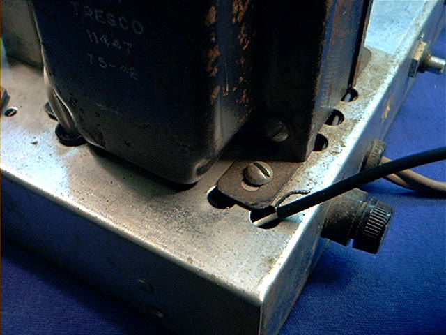
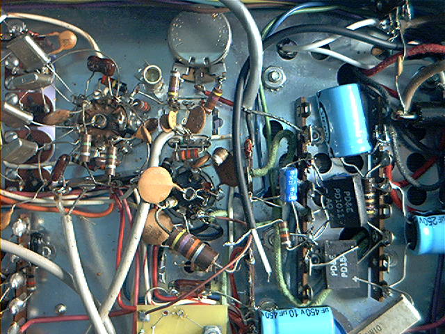
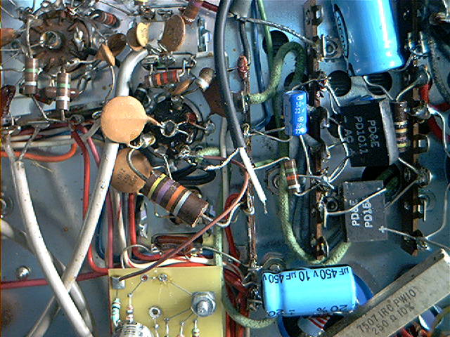
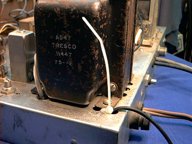
Under the radio, find the two
screws directly under the SSB
crystal filter. (see picture)
Slide a #4 inside tooth lockwasher over the
end of both the
filter screws.
 ,
,